Injection Molding is a widely used plastic manufacturing process to manufacture plastic parts in large volumes and at low cost. Plastic part design guidelines for injection molding ensure good quality manufactured parts.
This article covers various plastic part design guidelines for injection molding that you can implement in your part design to ensure good quality parts.
Why follow Plastic Part Design Guidelines for Injection Molding?
Your plastic part design should always ensure injection molded plastic part quality. We can achieve a wide injection molding window if the plastic part design is as per design guidelines. In other words, a part can accommodate more variation in the injection molding process.
But following all plastic part design guidelines for injection molding does not guarantee the best quality parts. Tool design, molding machine, and injection molding process parameters also impact part quality.
The Following factors affect the quality and consistency of injection molded plastic parts.
- Plastic Part Design
- Plastic Material
- Injection molding process parameters
- Injection molding machines
- Injection mold design
Plastic Part Design Guidelines
Plastic part manufacturers always recommend following the maximum possible design guidelines to manufacture defects-free plastic parts. But it is not possible to follow all design guidelines because of product design constraints.
Simulation studies (mold flow analysis for plastic parts) can reduce the risk when the plastic part design is not following all guidelines.
Following injection molding design guidelines have an impact on manufactured plastic part quality.
- Uniform Plastic Part Wall Thickness
- Plastic Boss Design.
- Rib Design Recommendation.
- Sharp Corners
- Gussets
- Draft Angle
1. Uniform Wall Thickness in Plastic Parts
Uniform wall thickness in injection molded parts ensures molten plastic is not passing through varying restrictions in the injection mold. Therefore it allows the injection mold cavity to fill more easily.
How Uniform Wall Thickness Will Improve Plastic Part Design?
When molten plastic passes into the variable cross-section injection mold, the thin plastic section starts cooling first. Afterward, when the thick section starts to cool, the injection-molded part shrinks, and built-up stresses near thin and thick section boundary areas.
The thin section does not yield because it has already hardened. Therefore when the thick-section yields, it leads to warping, twisting, shrinkage, or void formation in molded part. High stresses can also crack the molded plastic parts.
Therefore molder always recommends uniform wall thickness for defect-free injection molded parts.
Design Guidelines for non-uniform Plastic Part Wall Thickness
In design, it’s not always feasible to provide uniform wall thickness in all sections. Therefore following points are recommended to reduce the impact of non-uniform wall thickness.
- A gradual change in plastic part wall thickness.
- Avoid filling molten plastic from thin to thick sections.
- Remove plastic from thick-section (coring).
- Analyze the flow of molten plastic in thin sections.
2. Plastic Boss Design Guidelines on Plastic Parts
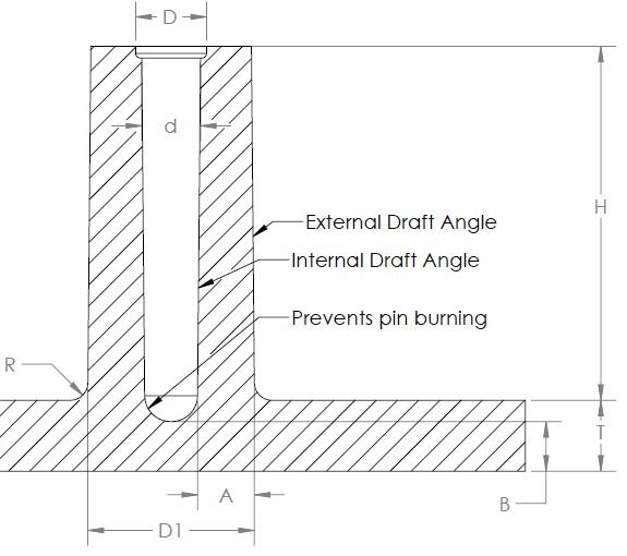
Product designers design boss features in plastic parts to receive screws, threaded inserts, or guide other parts. It consists of a cylindrical projection with holes.
During a product life-cycle, bosses come under various load conditions. Therefore Boss design in plastic parts should be as per guidelines to ensure boss strength and avoid injection molding defects.
Boss Wall Thickness
Recommended boss wall thickness is 0.6 times of nominal wall thickness of the plastic part.
Boss Wall Thickness (A) = 0.6 x T (Nominal Wall Thickness)
Note: We can increase Boss wall thickness to increase its strength. For example, in case of high stresses produced while using self-tapping screws. But this will have an impact on part aesthetics.
Radius at Boss Base
A small radius at the boss base increases boss strength and helps in part ejection during injection molding.
Recommended Radius at the base of boss feature (R) = 0.25 to 0.5 times of nominal wall thickness
Minimum center to center Distance Between Bosses
Small central distance between two boss features in plastic part design can result in a thick section. Thick sections are difficult to cool and result in injection molding defects. Therefore it is recommended to maintain a minimum spacing between bosses.
Minimum Center to center distance between Bosses = D1 + 2T
Where:
D1 – Boss Max Diameter
T – Nominal wall thickness
Draft Angle for Boss feature
Draft angle in injection molded parts helps in the easy removal of molded parts from the injection mold. Its Value depends on surface finish and boss height. Mostly 0.5º to 1º draft is recommended in the boss section.
Other boss Design Requirements
- You can add a Chamfer on the top of the boss hole for lead-in of fasteners.
- We can increase Boss strength by providing gussets at the base or connecting ribs to nearby walls.
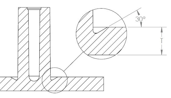
- As shown above, if the boss-wall thickness is more than recommended thickness. The recess around the base of the boss can reduce the probability of shrinkage.
3. Reinforcing Rib Structure Design in Plastic Parts
Ribs in plastic parts increase the part moment of inertia by increasing the bending stiffness. Therefore Ribs are used in plastic parts to increase bending stiffness without increasing plastic part thickness.
Bending Stiffness = E (young’s Modulus) x I (Moment of Inertia)
Rib Thickness Recommendation
In plastic part design, recommended rib thickness is 0.5 to 0.75 times the nominal wall thickness to avoid shrinkage in injection molded parts.
Rib Thickness (W) = 0.5 to 0.75 x T
Recommended distance between Two Ribs
To avoid thin sections in the injection mold. The recommended minimum distance between two ribs is two times of nominal wall thickness.
Distance between two ribs (X) > 2 x T
Draft Angle in Ribs
Draft angle in ribs ensures easy removal of injection-molded plastic parts from the injection mold.
Minimum Draft Angle in Outer ID = 0.5 degree
Minimum Draft Angle in inner ID = 0.25 degree
Rib Height
The maximum recommended rib height is less than three times of nominal wall thickness. Therefore avoid large variations in rib thickness in plastic part design. Multiple ribs are recommended instead of one large rib to increase bending stiffness.
Maximum Rib Height (H) < 3 x T
Sharp Corner Radius
Sharp corners at the rib base result in stress concentration. Therefore a minimum radius equal to 0.25 times of nominal thickness is recommended to avoid stress concentration after injection molding.
Rib Intersection in injection molded Part
Coring out rib at rib intersection is recommended to avoid excessive sinking on the opposite side of the rib.
Rib Orientation Recommendation
Orient A rib in a way it provides maximum bending stiffness to the part. Therefore Rib orientation depends on part geometry and bending load.
4. Sharp Corners in injection molded Plastic Parts
Sharp corners in plastic parts can lead to high stress, restrict material flow, and reduce part strength. Therefore it is recommended to add a radius in the plastic part design for injection molding.
Recommended inside corner radius in plastic pat design is more than 0.5 times the nominal wall thickness. Whereas recommended outside radius is inside radius plus nominal wall thickness.
The stress concentration factor at plastic part corners depends on its corner radius and nominal wall thickness.
The stress concentration factor is high if the ratio of the radius and thickness is less than 0.5. Therefore it is recommended to keep R/T values more than 0.5
5. Gussets In Plastic Parts
Gussets are used in plastic parts to increase part strength in the required section. But the location of gussets prevents direct venting in mold steel. Therefore Gussets in plastic parts should be designed in a way that they should not create any venting or filling problems.
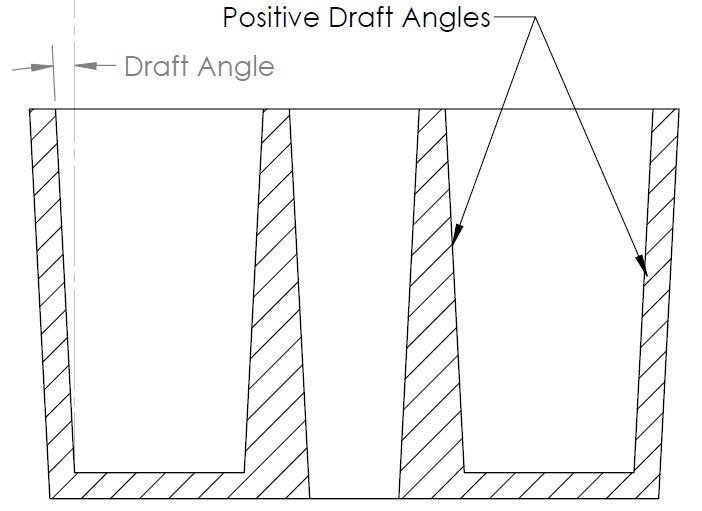
6. Draft Angle in Injection Molded Plastic Parts
Draft Angles are provided parallel to the direction of part release. It helps in the easy removal of the plastic part from the injection mold.
Higher the value of the draft angle, easy the removal of the part from the injection mold. Industrial designers will always ask for zero drafts, But mold designers need max possible draft angle.
Polished plastic parts require a relatively small draft angle compared to matte finish parts.
Factors Affecting Draft Angle Value
Following factors affect the value of draft angle:
- Feature Depth
- Feature Size
- Mold Finish
- Plastic Material
- Part Geometry
- Mold Ejection System.
Draft angle in Textures
Molder requires a minimum (1.5° + Part nominal draft angle ) per 0.025 mm texture depth for easy removal of parts.
To sum up, product designers shall injection molding plastic part design guidelines during plastic part design to ensure part quality and ease of manufacturing. It’s not feasible to follow all design guidelines. But wherever you can not follow design guidelines, you can reduce the risks by performing simulation studies.
We will keep updating injection molded plastic part design guidelines. Add your questions or comments on plastic part design in the comment box.
Add a Comment