What is Flatness Tolerance in GD&T?
Flatness in gd&t is a type of foam control GD&T tolerance. It controls the variations in a flat surface, regardless of any datum feature. In this way, it ensures the controlled surface is flat enough to perform the required function.
The flatness tolerance value is always less than the dimensional tolerance associated with the part feature. Don’t miss this article on the basics of Geometric Dimension and Tolerance.
Representation of Flatness Tolerance
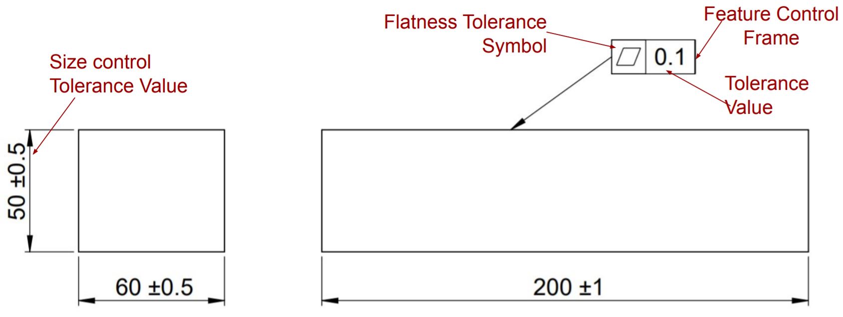
As shown above, a datum plane or features is not required to represent flatness. LMC and MMC modifiers can be used to provide bonus tolerance for the control feature.
Tolerance Zone
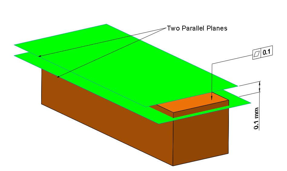
When applied to a surface, Flatness tolerance in gd&t creates a 3-dimensional tolerance zone of two equidistant parallel planes from the reference plane. All points of the feature surface must lie within this tolerance zone.
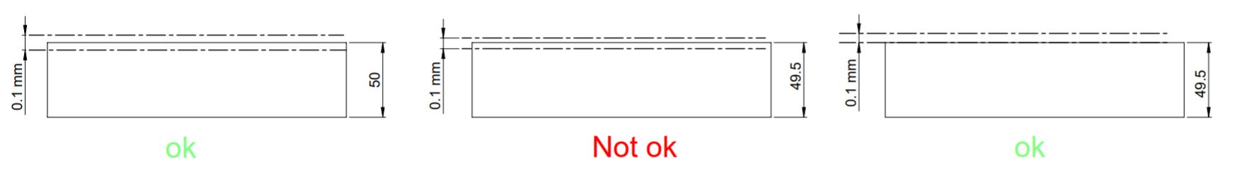
When we apply Flatness in gd&t to a surface, its value should be less than the size control tolerance.
Application Examples
Flatness tolerance in gd&t defines the waviness in part. It ensures smooth contact between mating or moving parts.
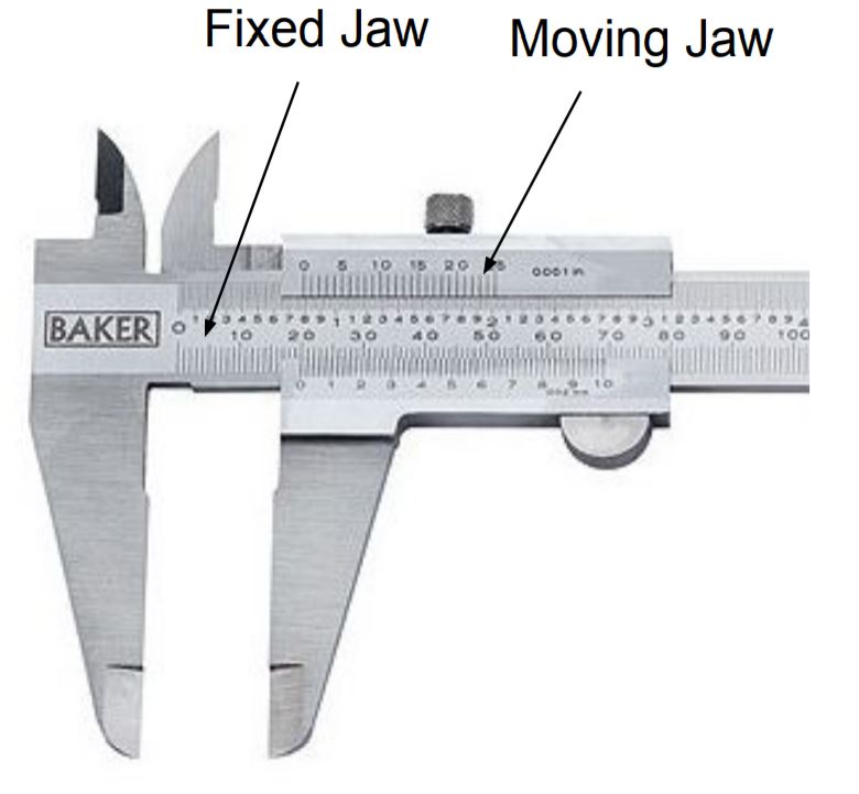
For example, Vernier caliper movable and fixed jaw needs to be flat to ensure its smooth operation. Without enough flatness, the movable jaw may be struck inside the fixed jaw.
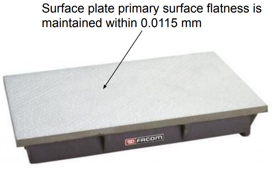
The primary surface of the Grade-0 surface plates is maintained flat in a tolerance range of 11.5 μm (0.0115 mm) per 2960 mm² area. It ensures the alignment of parts on the surface plate.
How to measure Flatness Tolerance?
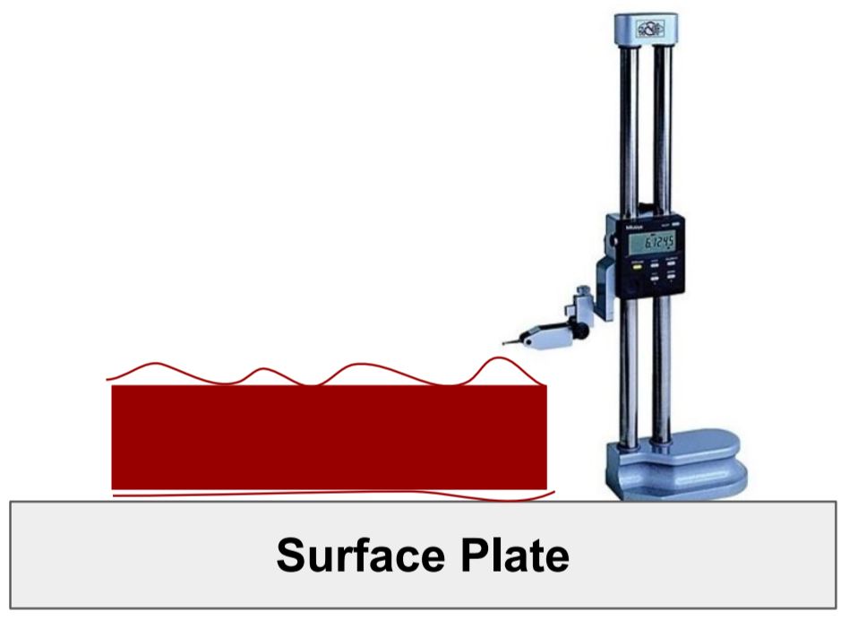
The arrangement shown in the above image will measure parallelism, not flatness. To measure flatness using a height gauge, You need to hold part control features parallel with the surface plate. But this arrangement is very difficult to achieve.
Therefore, modern CMM machines and 3D scanners are the best ways to measure flatness quickly. We can use these 3D scanners to generate 3D cad models from physical parts. In this way, you can measure the flatness in components using its CAD model.
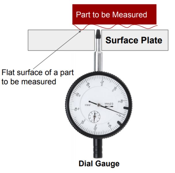
But if CMM machines and 3D scanners are not available. Flatness can also be measured using a dial gauge.
As shown in the above image, to measure flatness using a dial gauge, drill a through-hole in the surface plate. And dial gauge probe is passed through it.
To sum up, Flatness tolerance controls the flatness of a surface regardless of any datum feature. It makes a 3-dimensional tolerance zone. We suggest you read this article on Go No Go Gauges.
Got Questions? We will be happy to help.
If you think we missed Something? You can add to this article by sending a message in the comment box. We will do our best to add it to this post.
What is flatness tolerance in GD&T ? you mentioned type of foam control instead of form control. if i am wrong, correct me