Following 14 GD&T symbols are used to control foam, orientation, location, and runout in part geometry. Each of these GD&T symbols has its significance.
| Control Type | Description | Datum | Tolerance Zone | MMC LMC or RFS |
|---|---|---|---|---|
Form Control |
 Straightness
 | NA | Parallel Lines Plane or Cylindrical face | Feature of Size |
 Flatness
 | Parallel Plane | NA | ||
 Circularity
 | Parallel Lines | |||
 Cylindricity
 | Parallel Cylinders | |||
Profile Control |
 Profile of a Surface
 | Not Mandatory | Parallel Surfaces | |
 Profile of a Line
 | Parallel Lines | |||
Orientation Control |
 Perpendicularity
 | Required | Parallel Lines Plane or Cylindrical Zone | Feature of size |
 Angularity
 | Parallel Lines Plane or Cylindrical Zone | |||
 Parallelism
 | Parallel Lines Plane or Cylindrical Zone | |||
Location Control |
 Position
 | Parallel Plane or Cylindrical Zone | ||
 Concentricity control tolerance symbol
 | Cylindrical Zone | RFS Required | ||
 Symmetry
 | Parallel Plane | |||
Runout |
 Circular Runout
 | Parallel Lines | ||
 Total Runout
 | Parallel Cylinders |
Following additional symbols are used along with gd&t symbols to define a part geometry more accurately.
| Symbol | Description |
|---|---|

Datum Plane | Datum in GD&T is theoretical exact plane, axis or point from where GD&T tolerances are referenced to. |

Datum Target | Datum target is a point, Line or and area that is used to define the datum. |
Least Material Condition | "L" Symbol in GD&T is a feature of size symbol. It describes a dimensional or size condition where the least amount of material exists within given dimensional tolerance. |
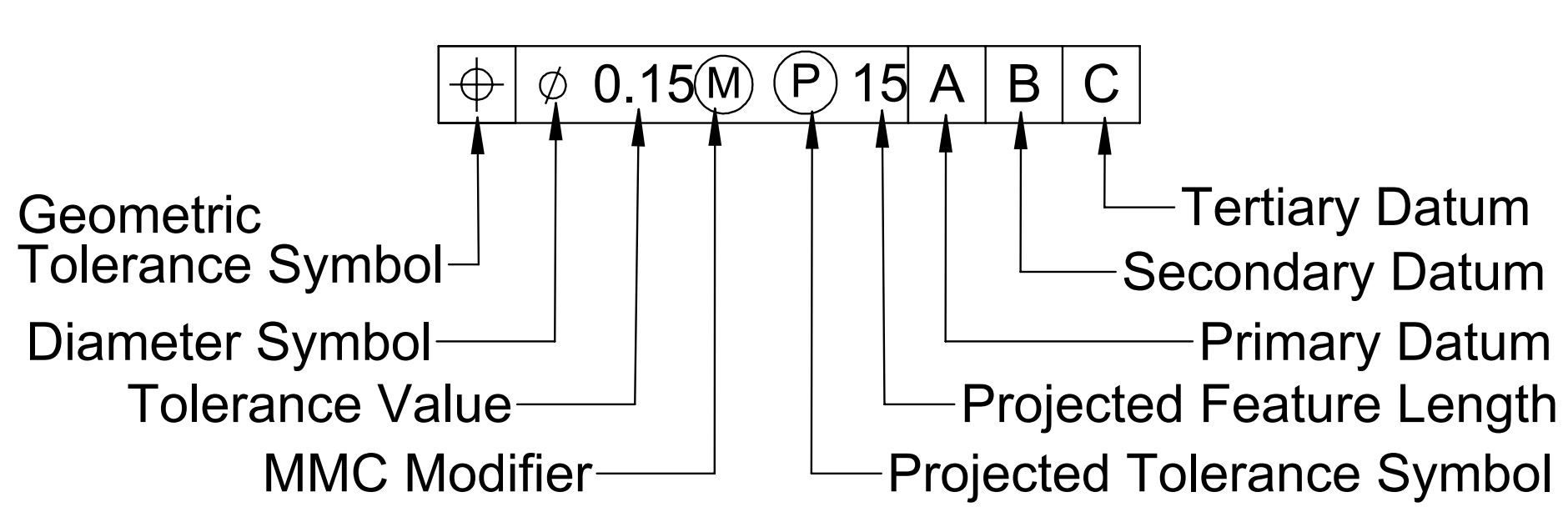
 Maximum Material Condition | "M" Symbol in GD&T is a feature of size symbol. It describes a dimensional or size condition where the maximum amount of material exists within given dimensional tolerance. |
 Projected Tolerance Zone | Projected tolerance zone is applied to a protuded feature. When indicated in drawing, it shows the zone where given GD&T tolerance is applicable. |
 Free State | Free State condition is used for non rigid parts such as rubber or foam parts. This symbol in GD&T indicates no force except gravitational pull should be applied in this region during measurements. |
 Tanget Plate | This symbol in GD&T indicates only the Tanget Plate of the of the controlled surface should be within this tolerance limits. |
Diameter | When defined in feature control frame diameter symbol in GD&T indicates that the defined tolerance is diametrical. |
Radius | When defined in feature control frame radius symbol in GD&T indicates that the defined tolerance is radial. |
 Controlled Radius | Controlled radius symbol creates a tolerance zone defined by two arcs tangent to the adjacent surfaces. |
 Statistically Controlled | It indicates the given dimension is statistically controlled. |
Add a Comment